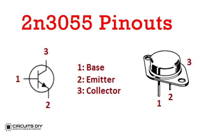
- 2n3055 transistor max base current how to#
- 2n3055 transistor max base current full#
- 2n3055 transistor max base current series#
pot must always obey the ratio relationship shown in the second attachment, meaning it cannot be allowed to be adj. Very bad if you turn the pot quickly, very bad if you turn the pot slowly over longterm use, especially bad for the pot near lowest voltage out.bad design! The v-adj. down from maximum or any set voltage, the power supply output capacitor is being discharged into the V-adj. The TIP is failing in your >2A tests.right? I don't understand with the circuit shown how you are not always going to be burning up the v-adj.
2n3055 transistor max base current series#
What you really need is a series high wattage resistor in series with the collector of the TIP100, having a value about 10 to 50 ohms. 100 to 150 ohms B-E resistors should be ok to prevent thermal runaway. Make sure you mount the TIP100 on a fairly large heatsink! See the attached spec sheet clip for base resistor values.
I don't want to wreck another pot because that was one of my favorite one's I can get the darn thing to a little over 2 amps but then every thing goes south. Rb=(V-Vbe)/Ib=(40-1.5)/4=154ohms Now since the transistors are parallel do I need to multiply that value by 4 from each transistor? I tossed in the schematic as well because when the transistor blows (only one because of the diodes from collector to emitter saved my back side) the voltage adjust potentiometer also blows.At least I'm not cratering the chip.
2n3055 transistor max base current full#
Nominal Design Procedure and Design Considerations : note 10 So that would give me 4amps at the base of the 2N3055's ( probably have that wrong as well)But I figured I'll use the maximum possible assuming the TIP 100 is is full saturation.I know its not good to assume. the reason is I need to have that gain (hFE 1000) to limit the draw from a regulator which needs to be around 0.5mAdc.This is explained in the data sheet of the regulator. It says Vbe is 1.5 or should it be 0.6 -0.7 Now the 2n3055's are being driven by a TIP100. Now to calculate the base resistor I need the hFE ( I've been using 5) The Vce is 1.5 (that's the voltage drop across collector and emitter?) Ic will been 4 amps. These are mounted on a fairly descent heat sink. According to the Active Region Safe Operating Area I should have around 2.5 amps at 40 volts. I would like 4 2N3055's to share the 4 amps (1 amp each). I have 4 amps from the transformer at 40 volts. Just need to get the Math right!! These are the parameters I'm working with. I would like to try to get this working with the components I have ,then make improvements as better ones become available. My problem is my math is so rusty that I'm not sure if I'm getting this right or even if I'm using the right values from the data sheet.
2n3055 transistor max base current how to#
So I need to add a base resistor as well.Since I'm using a well know transistor (the 2n3055) theirs more information on how to calculate the resistors.


I think I know now what my problem is in balancing parallel transistors.I'm getting confused about what values of resistor I need at the emitter and base.Now clearly a 0.1 ohm resister at the emitter is not doing the job of limiting load hogging.I'm burning transistors to much and it sucks.


 0 kommentar(er)
